

Types of Protection Relays – A Complete Technical Guide
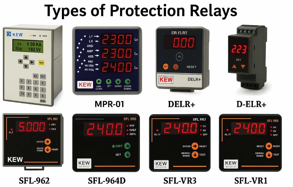
Types of Protection Relays – A Complete Technical Guide
Protection relays are like the immune system of a power network each type is designed to sense a specific abnormality and respond instantly. While they all serve the same ultimate purpose protecting life, equipment, and system stability the way they achieve it varies according to the fault they are designed for. Let’s explore the major types of protection relays, how they work, and where they are used.
Types of Protection Relays
Given below are the Types of Protection Relay
- Overcurrent Relay
- Differential Relay
- Distance Relay
- Overvoltage Relay
- Over frequency Relay
- Directional Relay
- Earth Fault Relay
- Transformer Differential Relay
- Generator Protection Relay
- Motor Protection Relay
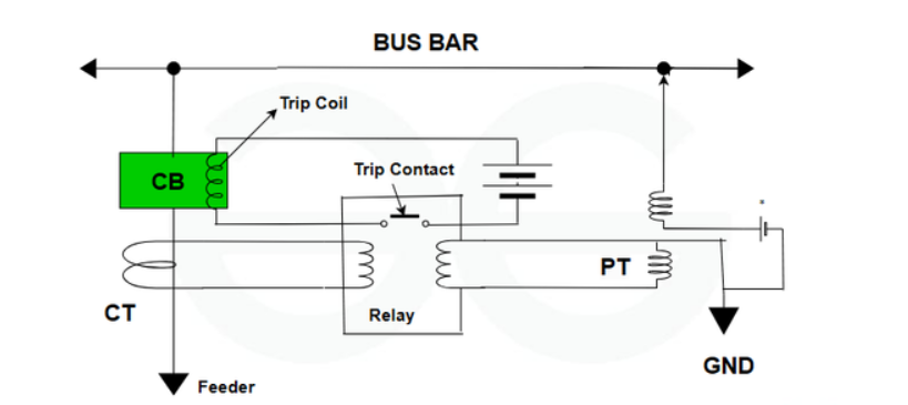
1. Overcurrent Relay (OCR)
The overcurrent relay is responsible for protecting the system from heavy current flow. It facilitates the protection of electrical equipment and systems from damage caused by overloading, short circuits, and other anomalous conditions. If the current increases the threshold value for a particular duration of time, the relay will send a trip single that will interrupt the circuit, this will isolate the circuit from the faulty area with defined boundaries. These can recognize various types of malfunctions, including short periods of inactivity, overburden, and ground-based malfunctions. They have a significant impact on maintaining the stability of the device and preventing it from experiencing malfunctions.
Principle: Operates when the current exceeds a preset limit.
Working: Current transformers (CTs) continuously measure the current. When current surpasses the threshold for a set time, the relay sends a trip command to the circuit breaker.
Applications: Used in distribution systems, feeders, motors, and backup protection in transmission lines.
Types:
Instantaneous OCR → trips immediately when the limit is crossed.
Inverse-time OCR → tripping time reduces as fault current increases.
Example: Protecting distribution feeders from overloads or short-circuits.

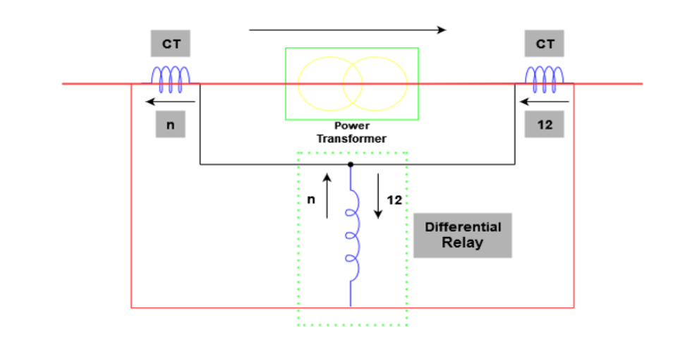
2. Differential Relay
To identify problems, this device compares the current entering and leaving the protected area. According to this principle, a defect causes a difference in current entering and leaving the area, activating the relay and isolating the problematic section. In contrast to overcurrent relays, differential relays compare the current at two points. If the currents (input and output currents) are not equal, the circuit is unbalanced and a fault may exist, thereby isolating the faulty part from the main circuit. According to the principle of Kirchhoff’s current rule, which states that the sum of the currents entering and leaving each node must be equal under normal circumstances. Differential relays are highly sensitive and provide fast and selective protection, minimizing damage to equipment and reducing downtime.
Principle: Compares currents entering and leaving a protected zone. Any difference indicates a fault.
Working: Based on Kirchhoff’s Current Law (KCL) — current entering = current leaving. If difference exceeds a threshold, the relay trips.
Applications: Widely used for transformer protection, generator protection, busbars, and motors.
Special Feature: Extremely sensitive and fast because it only trips for faults inside the protected zone (unit protection).
Example: Transformer internal winding short-circuit detection.
3.Distance Relay (Impedance Relay)
The relay works by gauging impedance to define the exact distance to an issue. Commonly known as impedance relays, these distance relays work effectively in sizing up and pinpointing the complications with impedance or separation between a relay and problematic point within the power grid. They function by comparing an actual impedance value of the safeguarded line against a predefined curve; should they find any discrepancies marking recorded measurements outside this preset curve, it implies there is a complication at hand.
Principle: Operates based on the measured impedance (Z = V/I) between relay location and fault point.
Working: Relay calculates impedance from voltage and current signals. A low impedance indicates a nearby fault; higher impedance indicates a distant fault.
Applications: Primary protection in high-voltage transmission lines.
Zones:
Zone 1 → Immediate tripping for nearest section.
Zone 2, Zone 3 → Backup for farther sections with time delay.
Example: Detecting line-to-line faults in a 220 kV transmission line.
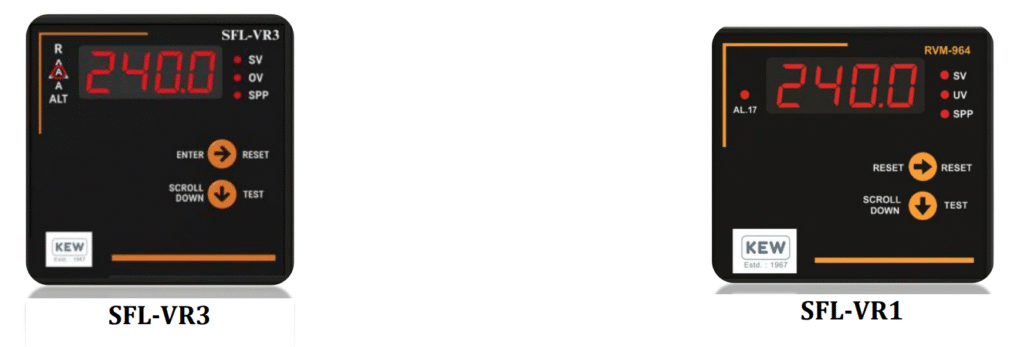
4. Overvoltage Relay
Overvoltage relay are the guards in electrical systems needed to protect against the chances of having abnormal high voltage levels. They are constantly monitoring the factors like voltage and relying on their well-established mechanisms such as the tripping circuit breakers to prevent dangerous system failures. Relays can provide a means to generate trip signal as a result of overvoltage incidents wherein the downstream protection trips are sent to isolate the faulted section of the equipment. It prevents damage of electrical systems, thus guarantees the safety of the system’s equipment, and its reliability in delivering uninterrupted power supply. Mostly, the type of equipment urged by voltage surges from lightning, switching and transient interferences rely on overcurrent relays.
Principle: Operates when system voltage rises above a set limit.
Working: Voltage transformers (VTs) monitor line voltage. Relay compares actual value with threshold; if exceeded, tripping occurs.
Applications: Protects generators, motors, capacitor banks, and insulators from insulation failure and overexcitation.
Example: Protecting a capacitor bank from dangerous overvoltage due to switching transients.
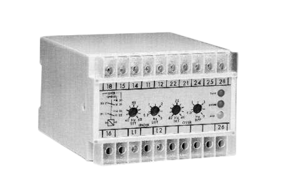
5. Overfrequency Relay
The higher frequency relay in electrical power networks operates and react to at moment where there is abnormal high frequency in the power circuit, by tripping circuit breakers or disconnecting the equipment for the purpose of system stability is being triggered. The relay buffer safeguards the system in the case of a fault by means of insulation from the deranged section of the system. As the system frequency exceeds this certain threshold value, the relay signal is given, and the involved part is de-energized like that of other protection approaches. It prevents damage from large and high frequency waves and also limits the probability of noise interference due to the high level of the exposure that is usually imposed by the overvoltage conditions.
Principle: Operates when system frequency rises above the safe operating band.
Working: Relay senses system frequency through voltage waveform analysis.
Applications: Protects generators and turbine-driven machines from mechanical stress and instability.
Importance: Overfrequency usually happens when load suddenly decreases while generation remains constant.
Example: Power plant generator protection during sudden load drop.
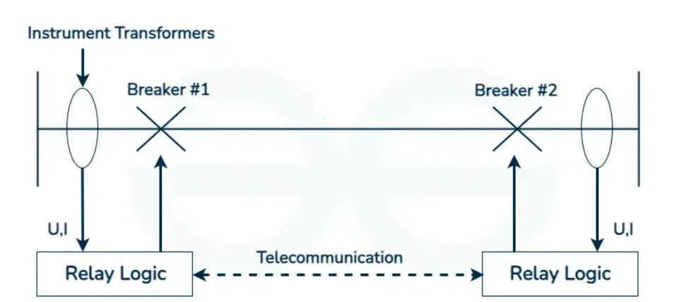
6. Directional Relay
Directional relays determines differential angles between fault current coming from the problematic area and the reference angle of the protected area behind the relay. The directional relay compares these two angles, and the fault is isolated if the differential angle is greater than preset value. This helps to detect the fault by measuring the upstream or downstream flow of current. There are different types of directional relays based on their method of operation and application, including:
- Overcurrent directional relays: Useful when the current flow is the bottom-most direction.
- Distance directional relays: Unite directional power sensing and distance protection.
- Power directional relays: Use power flow monitoring to locate and fix faults or unbalance conditions
Principle: Responds not just to magnitude but also the direction of power flow.
Working: Uses both voltage and current inputs. The relay determines the phase angle between them to identify the direction of fault current.
Applications: Used in parallel feeders, interconnected lines, and ring networks, where power flow direction is important.
Example: Preventing false trips when power flows in reverse direction during network switching.
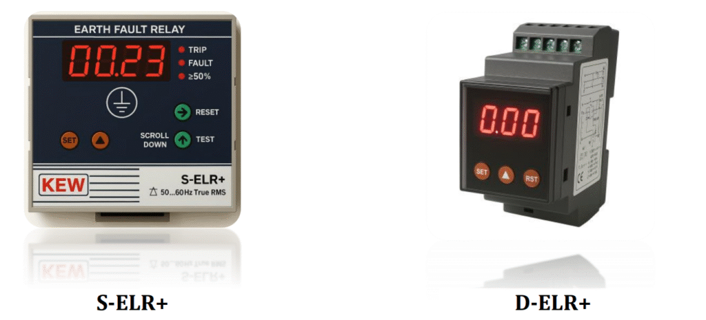
7. Earth Fault Relay
The earth fault relay is used in electrical systems for the purpose of protection against faults, which involve breakage or connection that extends from the earth (ground) to an electric circuit. It deals with equipment damage, electrical shocks, and fires since it cuts the circuit on locating a fault. Earth fault relays has a configuration with selective settings. Also, a critical activity of this operation, is specially done so that the disruption is minimized to other segments of the electric grid which are still in operation. These earth faults relays are multiple in their way of operation, and therefore, the application. Some of the relays are based on the residual current which flows in the system’s neutral conductor; the others are based on the detection of small fault current to the ground, and the other last type are based on the large fault current which flows to the ground with low resistance.
Principle: Operates when leakage current flows to ground due to insulation failure.
Working: Relay measures residual current using a core-balance CT (summing phase currents). Non-zero residual current indicates ground fault.
Applications: Protects cables, transformers, and motors against insulation breakdown and fire hazards.
Example: Detecting ground faults in low-voltage distribution systems.
8. Transformer Differential Relay
These relays deal with the faults in the system by comparing two current values. If any imbalance occurs in the normal operation, these relays trips to ensure the safety and reliability of the system. It continuously monitors the flow the flow of current through the transformer windings. It compares the currents using a current transformer (CT) on each side of the transformer (primary and secondary) to measure the current imbalance. Transformer differential relays are configured with appropriate settings to ensure that only the faulty zone or section is isolated from the main system. This selective operation helps minimize downtime and reduces the distortions to the rest of the electrical network.
Principle: Specialized differential relay designed for transformers.
Working: Compares currents on primary and secondary windings, compensating for CT ratio and phase shift.
Applications: Provides selective protection only for internal transformer faults.
Special Features: Inrush restraint logic (to avoid tripping during magnetizing inrush current).
Example: Detecting inter-turn short circuits in a 132/33 kV transformer.
9. Generator Protection Relay
These relays are designed to safeguard the generator network and components and protects a reliable function of the generator device. Temperature protection monitors the temperature of critical components such as stator windings, rotor windings, and bearings to prevent overheating and thermal damage. To ensures specific working; generator protection relays are frequently synchronized with other protective components in the power system. Thus, it minimizes the disturbance to the rest of the network during a problem by ensuring that only the damaged area of the system is isolated.
Principle: Provides multi-function protection to generators against electrical and mechanical faults.
Working: Includes multiple elements — differential protection, overvoltage, under/overfrequency, loss of excitation, rotor earth fault, etc.
Applications: Ensures safe operation of synchronous generators in power plants.
Example: Tripping a generator during loss of excitation to prevent pole slipping and system instability.
10. Motor Protection Relay
Motor protection relays protect electric motors from overload, phase imbalance, overcurrent, and short circuit by monitoring electrical system characteristics and causing the motor to be shut off if abnormal conditions are detected. External sensors or temperature sensors are built into the motor to measure the temperature of the motor windings, which prevents the motor from thermal damage, and the motor trips whenever it senses overheating conditions due to excessive current or other source. It is necessary to maintain a proper balance between the current and phase of the motor. Any imbalances lead the motor to overheat and experience mechanical stress. In order to prevent motor damage, the relay detects phase unbalance and starts protective measures.
Principle: Protects motors against abnormal electrical and thermal stresses.
Working: Monitors parameters like overcurrent, phase imbalance, single-phasing, stalling, and overheating.
Applications: Used in industrial motors driving pumps, conveyors, compressors, etc.
Special Features: Thermal modeling to prevent insulation damage.
Example: Protecting an induction motor from burning during prolonged stalling.
Final Thoughts
Every type of protection relay is like a specialist doctor — one detects fever (overcurrent), another checks heartbeat (frequency), another monitors blood pressure (voltage). Together, they form a comprehensive shield for power systems. Without them, modern grids would collapse under the first serious disturbance.
Recent Posts
Future Innovations in Protection Relays: Shaping the Next-Gen Power Systems

Applications of Protection Relays in Real-World Electrical Systems