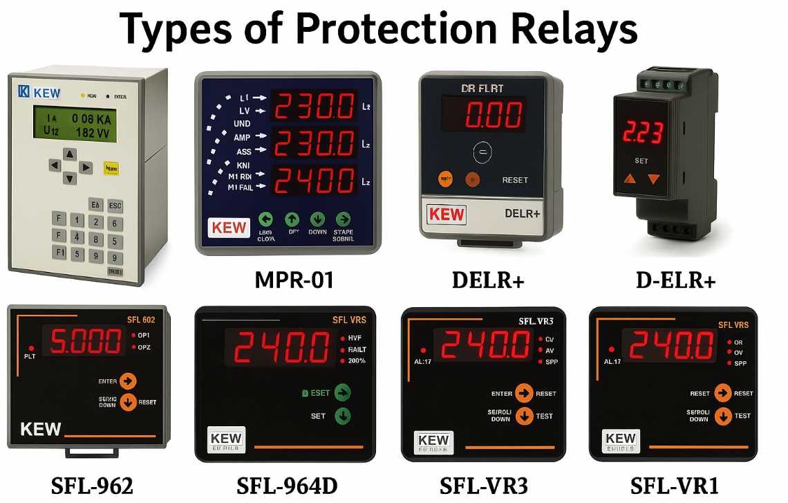

Working of Protection Relay – A Deep Technical Guide
This article is dedicated solely to the working principle of protection relays. Think of them as the silent guardians of our power systems — always awake, always watching. These devices keep a constant eye on voltage, current, frequency, and the overall health of the grid in real time.
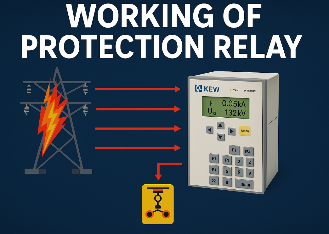
But here, we go beyond just introductions. We’ll walk through the step-by-step process of how a relay actually works — how it detects when something is wrong, how it decides whether the disturbance is serious, and how it commands circuit breakers to isolate the problem before it spreads.
The beauty of a relay lies not only in its speed, but in its intelligence. It can tell the difference between harmless momentary disturbances and dangerous permanent faults. Without this judgment, even a tiny short-circuit could spiral into a large-scale blackout or costly equipment damage.
In this guide, we’ll break down how protection relays sense, analyze, decide, and act. We’ll also explore how modern relays use digital processing, coordination, and advanced features to make today’s power systems smarter, more reliable, and more secure.
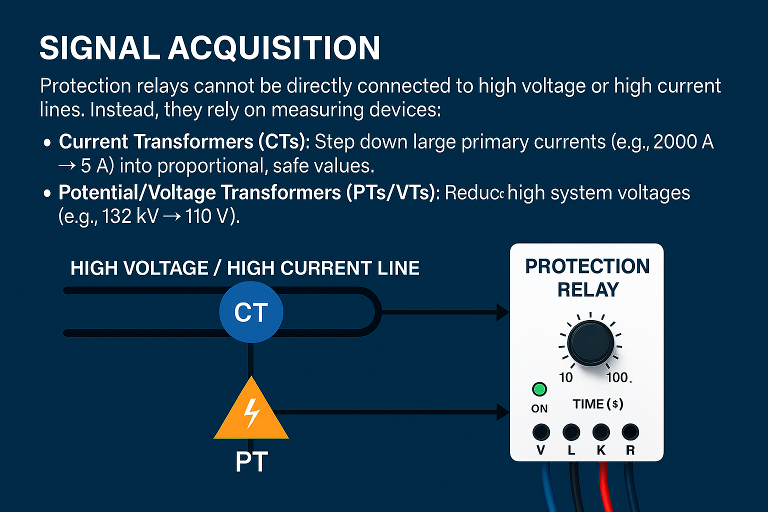
1. Signal Acquisition
Protection relays cannot be directly connected to high voltage or high current lines. Instead, they rely on measuring devices:
Current Transformers (CTs): Step down large primary currents (e.g., 2000 A → 5 A) into proportional, safe values.
Potential/Voltage Transformers (PTs/VTs): Reduce high system voltages (e.g., 132 kV → 110 V).
These CTs and PTs act as the relay’s eyes and ears, constantly feeding it with real-time system conditions. The accuracy of these devices is critical, because even a small error in measurement could lead to false trips or failure to detect a dangerous fault. Modern digital relays often compensate for CT/PT errors internally, ensuring precise fault detection.
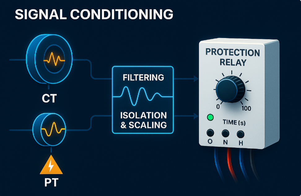
2. Signal Conditioning
The raw signals from CTs and PTs are not always clean. They may contain noise due to switching surges, lightning impulses, or harmonics from nonlinear loads. Hence, the relay applies:
Filtering: Removes high-frequency noise and harmonics.
Isolation and scaling: Brings signals to a safe range for further processing.
This ensures the relay works with stable and reliable input data. In advanced systems, adaptive filters are even used to distinguish between fault currents and temporary disturbances like motor starting or transformer energization.
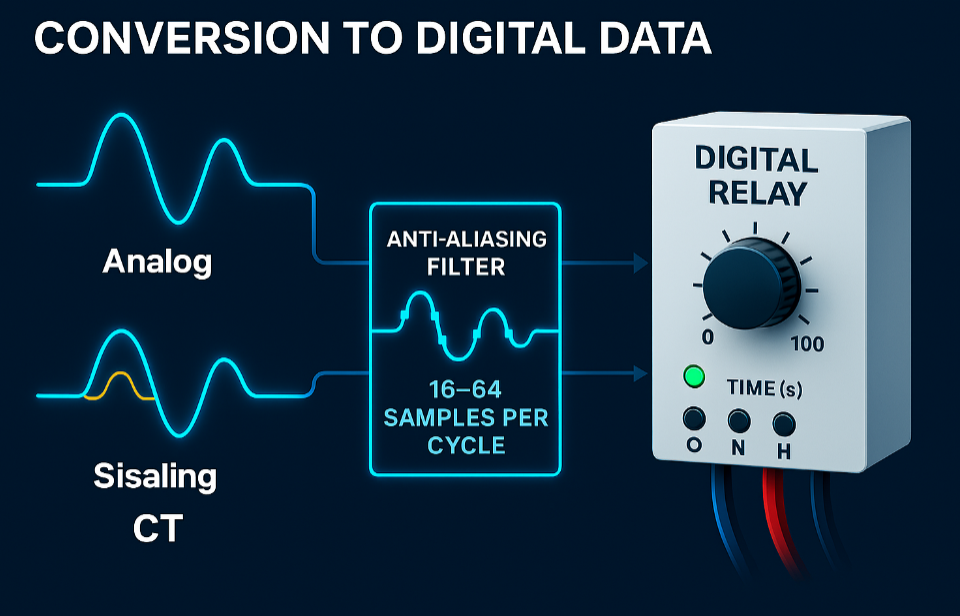
3. Conversion to Digital Data
Lorem ipsum dolor sit amet, consectetur adipiscing elit. Ut elit tellus, luctus nec ullamcorper mattis, pulvinar
Modern relays are digital. Once signals are conditioned, they are sampled at high rates, typically 16–64 samples per cycle in a 50 Hz system. Each sample represents the instantaneous value of current or voltage.
Before conversion, anti-aliasing filters prevent waveform distortion. Once digitized, the relay now has numerical data that can be processed mathematically. The higher the sampling frequency, the faster and more accurately the relay can detect fault characteristics, which is essential in high-speed protection schemes like busbar or generator protection.
dapibus leo.
4. Digital Signal Processing
This is the heart of modern relays. Using microprocessors or DSP (Digital Signal Processors), the relay extracts key electrical quantities:
RMS Value Calculation: Determines the effective value of current or voltage.
Phasor Estimation: Identifies the magnitude and phase angle of fundamental frequency components.
Impedance Calculation: By dividing voltage by current, the relay estimates impedance. Low impedance indicates a nearby fault.
Differential Current Comparison: Compares current entering and leaving an equipment section. A mismatch indicates internal fault.
Harmonic Analysis: Identifies the presence of 2nd harmonics, which helps distinguish transformer inrush currents from faults.
Advanced relays may also perform frequency analysis, sequence component separation (positive, negative, zero sequence), and real-time event recording, which helps engineers later analyze why and how a fault occurred.

5. Decision Logic
The relay continuously compares processed values with its preset settings. These settings are configured by protection engineers based on system studies. The decision logic works as follows:
Overcurrent Protection: Trips if current exceeds the pickup setting for a defined time.
Differential Protection: Trips if difference between incoming and outgoing currents exceeds limit.
Distance Protection: Trips if measured impedance falls within the set protection zone.
Directional Protection: Checks the angle between current and voltage to determine the direction of fault power flow.
Modern relays are intelligent: they avoid tripping for temporary swings, auto-reclose circuits after transient faults, and use multiple criteria (like voltage drop + current rise) before making the final decision.
6. Trip Command Execution
Once a fault is confirmed, the relay sends a trip signal to the trip coil of the circuit breaker. This energizes the breaker mechanism, causing its contacts to open. When the breaker opens:
The fault current path is broken.
The arc generated at contacts is extinguished using air, SF6 gas, or vacuum.
The faulty section is isolated, while the healthy system continues operating.
This action typically happens within 20–100 milliseconds. To put it in perspective, that’s faster than a blink of an eye — yet powerful enough to save multimillion-dollar equipment and maintain grid stability.
7. Relay Coordination
Relays are not designed to act alone; they work as part of a coordinated protection scheme:
Primary Protection: Closest relay to fault should act first.
Backup Protection: If primary fails, backup relay trips after a small time delay.
Zone Coordination: Transmission lines, transformers, and feeders each have defined zones of protection with slight overlaps to ensure complete coverage.
Relay coordination is like teamwork — ensuring that only the faulty section is removed while the rest of the system keeps running. Without coordination, a minor fault on a feeder could cause the entire substation to trip, leading to unnecessary blackouts.
Complete Working Flow
The full working process of a modern protection relay can be summarized as:
Fault occurs → abnormal current or voltage.
CTs and PTs sense fault signals.
Signals are filtered and scaled.
Converted to digital samples.
Algorithms process samples (RMS, phasor, impedance, harmonics).
Relay compares results with settings.
Decision logic confirms fault.
Relay energizes breaker trip coil.
Breaker opens → fault isolated.
All of this happens in a fraction of a second, keeping the system stable and safe. The relay also records the fault details for engineers to analyze later, ensuring long-term system improvement.
Conclusion
The working of a protection relay is not just about tripping a breaker; it is a sophisticated chain of sensing, conditioning, analyzing, decision-making, and execution. By combining high-speed electronics, digital processing, intelligent logic, and advanced communication, modern relays act as the brain and nervous system of the electrical grid. They not only protect equipment but also ensure uninterrupted power supply to industries, hospitals, data centers, and households.
Recent Posts
Future Innovations in Protection Relays: Shaping the Next-Gen Power Systems

Applications of Protection Relays in Real-World Electrical Systems